Protecting a MOSFET requires more than adding one Zener diode. A reliable design keeps gate-to-source voltage, drain-to-source voltage, current, junction temperature, and switching energy inside their limits during normal operation and foreseeable faults. It also provides a safe path for energy stored in wiring, motors, transformers, and capacitors.
Begin with the actual failure scenario. A gate-oxide puncture, inductive drain spike, hard short circuit, linear-mode hotspot, overheating event, and false turn-on each need a different response time and protection element.
Protect the gate oxide
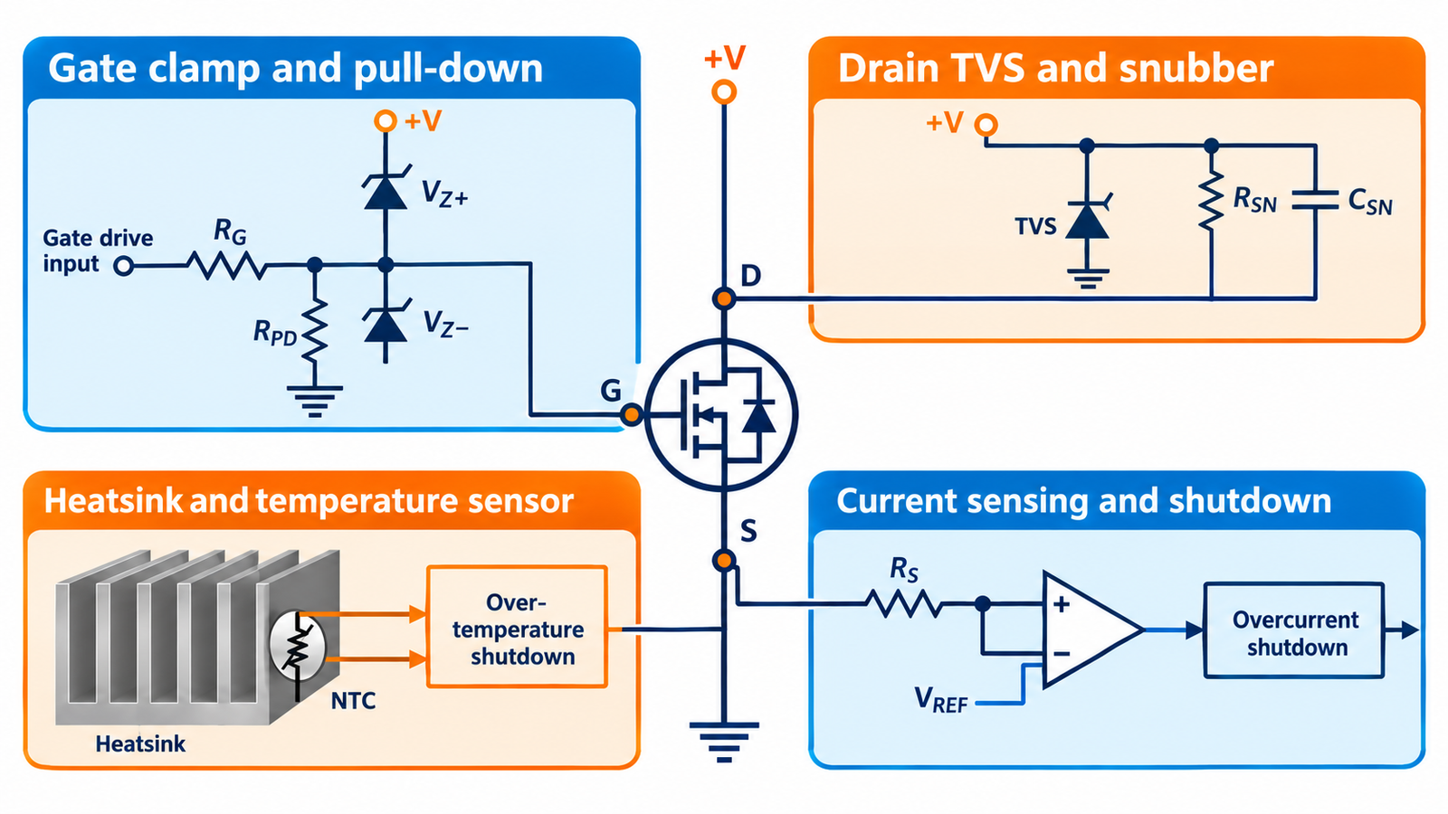
Keep VGS below the data-sheet absolute maximum in both positive and negative directions. Use a driver with controlled output, a short gate loop, a gate-to-source pull-down, and—where transients justify it—a properly selected gate clamp placed close to the pins. A resistor controls peak gate current and damps ringing but does not by itself guarantee a safe voltage.
The focused guide to gate-oxide voltage margin explains why normal drive should not sit against the absolute maximum.
Limit drain-source overshoot
Turn-off current flowing through stray inductance creates L·di/dt voltage. Reduce the commutation-loop area, place bypass capacitors close to the switching cell, and control edge rate. Use a freewheel path, RCD snubber, TVS, active clamp, or avalanche-rated device according to the energy, repetition rate, and required current decay.
A clamp voltage must stay below the MOSFET rating with margin while remaining high enough for the load to release as required. Probe at the MOSFET pins; a distant test point can miss local overshoot.
Stop overcurrent quickly
A fuse protects wiring and prevents sustained fire energy, but it is usually too slow to keep a semiconductor inside its short-circuit limits. Add cycle-by-cycle current limiting, a shunt or current-sense element, driver desaturation or smart-switch protection when applicable, and a controlled latch-off or retry policy. Blanking must reject switching spikes without masking a real fault.
Check current at startup, capacitor charging, motor stall, and load short. These can differ greatly from normal running current.
Manage heat and linear operation
Calculate conduction, switching, diode, and gate-drive losses at the hot operating point. Provide a characterized junction-to-ambient path using PCB copper, thermal vias, a heatsink, or airflow as appropriate. Temperature sensing can initiate derating or shutdown before the junction reaches its limit, but sensor lag and physical distance require margin.
A MOSFET can fail below its current rating when voltage and current coexist in linear mode. Always check DC and pulsed SOA for hot-swap, inrush, current limiting, and slow gate ramps.
Prevent false turn-on and shoot-through
High drain dV/dt can couple through the Miller capacitance and lift the gate. Use low-inductance source return, suitable turn-off impedance, Miller clamp or negative bias when justified, and controlled dead time in bridge circuits. Avoid excessive negative gate voltage caused by common-source inductance.
See dV/dt protection methods for driver and layout choices that address this dynamic failure mode.
Coordinate protection and recovery
Define what happens after a fault: immediate retry, timed hiccup, limited retries, or latched shutdown. Repeated avalanche or short-circuit attempts can accumulate heat even when each individual pulse seems tolerable. Ensure the controller remains biased predictably during brownout and that an unpowered driver cannot leave the gate floating.
Review single-pulse versus repetitive avalanche before using avalanche capability as a routine clamp.
Turn the answer into a robust MOSFET design
For How to Protect a MOSFET, create an operating-state table before choosing a device or protection value. Include off, startup, steady on, PWM transitions, shutdown, reverse current, load connection, controller reset, brownout, open load, overload, and short circuit. For each state, write the expected VGS, VDS, current, duration, repetition, and starting temperature. This exposes short but severe events that an average-current calculation hides.
Next, compare the table with guaranteed data-sheet limits and characterized curves. Use voltage margin for supply tolerance and ringing; use RDS(on) at the actual gate voltage and hot junction; use total gate charge and Miller charge for driver sizing; and use DC or pulsed SOA for intervals where voltage and current coexist. Include package, PCB copper, interface material, airflow, connector, and source-return inductance in the model. A transistor cannot be evaluated separately from its commutation path and gate loop.
Build a staged test plan that begins with limited available energy. Capture gate-to-source voltage at the pins, drain-source voltage, current, and temperature while changing one stress at a time. Repeat enough cycles to reveal cumulative heating and recovery behavior. Define pass limits before looking at the waveform, preserve oscilloscope files, and record device lot, ambient, probe method, and firmware revision. If measured peaks approach an absolute maximum, redesign for margin rather than accepting the result because one prototype survived.
Practical validation checklist
Validate at the worst credible supply voltage, load current, switching frequency, ambient temperature, and fault condition. Measure gate-to-source voltage at the device pins, drain-to-source voltage with adequate bandwidth, current, case temperature, and—when power or pulses are significant—estimated junction temperature. Account for probe ground inductance and avoid interpreting ringing created by the measurement setup as circuit behavior.
Compare every result with the data-sheet safe operating area, absolute maximum ratings, transient thermal impedance, and temperature-dependent curves. Test startup, shutdown, load connection, stalled or shorted load, controller brownout, and repeated operation. The guides to reading MOSFET safe operating area and MOSFET thermal calculation provide useful companion checks.
Frequently asked questions
Will a fuse protect a MOSFET?
It helps protect wiring and limits sustained fault energy, but semiconductor short-circuit protection usually needs a much faster electronic response.
Is a gate resistor enough protection?
No. It shapes switching and damping; separate measures may be needed for VGS clamping, drain transients, overcurrent, and temperature.
Can I rely on MOSFET avalanche rating?
Only after checking pulse energy, starting junction temperature, current, repetition, lifetime, and the manufacturer’s characterization.
Where should a TVS be placed?
Close to the current loop and nodes it protects, with short low-inductance connections and a voltage rating coordinated with the MOSFET and system.